Introduction
- What is EGG?
- Why EGG?
- Graph-based representation of individuals
- Subgraph-based operations
- EGG system framework
- EGG applications
What is EGG?
Evolutionary Graph Generation (EGG) is a unique variation of evolutionary computation techniques. The key features of EGG are to employ general graph structures as individuals and to introduce new evolutionary operations for manipulating the individual graph structures directly without encoding them into other representations, such as bit strings used in Genetic Algorithm (GA) and trees used in Genetic Programming (GP). The EGG application includes (but is not limited to) the evolutionary design of electronic circuits.
Why EGG?
There are two types of well-known evolutionary optimization techniques "Genetic Algorithm (GA)" and "Genetic Programming (GP)". Although these two techniques have been applied to a large variety of practical problems, they are not suitable for handling general graph structures directly. The reason is that they employ bit strings or trees for representing individuals. To evolve graph structures such as electronic circuits efficiently, the proposed EGG system is designed to transform the individual graph structures directly by exchanging their compatible subgraphs. Our experimental observation indicates that the subgraph-based crossover and mutation operations, newly introduced in the EGG system, are useful for many circuit synthesis problems.
Graph-based representation of individuals
The EGG system employs circuit graphs as individuals. A circuit graph consists of nodes and directed edges. Nodes are of two classes: functional nodes and input/output nodes. Every node has its own name, the function type and input/output terminals. We assume that every directed edge must connect one output terminal (of a node) and one input terminal (of another node), and that each terminal has one edge connection at most. A circuit graph is said to be complete if all the terminals have an edge connection. In synthesizing electronic circuits, all the circuit graphs used in the EGG system are at least complete circuit graphs.
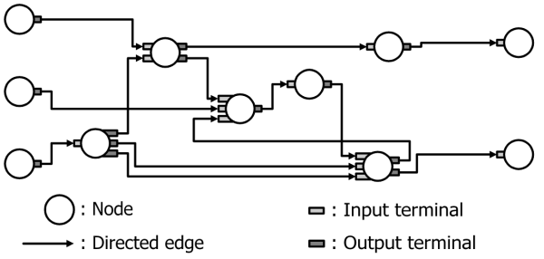
Figure 1. Circuit graph.
Subgraph-based operations
The EGG system employs two basic evolutionary operations, crossover and mutation, to transform the structure of circuit graphs. The crossover operation, illustrated in Figure 2 (a), recombines two parent graphs into two new graphs. When a pair of parent graphs Gp1 and Gp2 is selected from the population, the crossover operation determines a pair of sub-circuit graphs Gp1' and Gp2' to be exchanged between the parents, and generates offsprings Gc1 and Gc2 by replacing the sub-circuit graph of one parent by that of the other parent. In this process, the system selects a sub-circuit graph Gp1' randomly from the mother circuit graph Gp1, and selects a compatible sub-circuit graph Gp2' from the father circuit graph Gp2, where "compatible" means that the cutsets for these sub-circuit graphs contain the same number of edges for both negative and positive directions. This ensures the completeness of the generated offsprings. (Click here for animated example of crossover operation.) The mutation operation illustrated in Figure 2 (b), on the other hand, partially reconstructs the given circuit graph. When a parent graph Gm is selected from the population, the mutation operation determines a sub-circuit graph Gm' randomly, and generates a new offspring Gn by replacing Gm' with a randomly generated sub-circuit graph Gn'. In this process, Gn' must be compatible with the original sub-circuit graph as shown in Figure 2 (b). (Click here for animated example of mutation operation.)
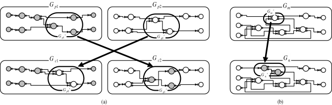
Figure 2. Evolutionary operations: (a) crossover, (b) mutation.
EGG system framework
We have designed a generic object-oriented framework for the EGG system, which is called "EGG framework". Figure 3 illustrates the class diagram of the EGG framework, where each rectangular box represents a class template (or a class) and each dashed rectangle shows template arguments. These framework class templates (and a class) contain fundamental components for the EGG system. The overall work-flow is controlled by the Control class template, which is associated with Population, Mutation, Crossover, Selection and Evaluation class templates. The Population class template contains the basic individual model defined by the Graph class template. The class templates Mutation, Crossover, Selection and Evaluation define basic operators for Population objects. The Graph class template has Node, SubGraph and Fitness, where Node and SubGraph inherit from the AbstractNode class template. The AbstractNode has the Terminal class template. The connecting edge at the Terminal class template indicates an "association", i.e., one Terminal object calls another Terminal object to define the network topology. In order to synthesize bit-serial arithmetic circuits, for example, we have created 6 new classes inheriting from Graph, SubGraph, Node, Terminal, Fitness and Evaluation, respectively. The EGG system can be systematically modified for different design problems by inheriting the framework class templates. For more details, click here for the technical documents of EGG framework.
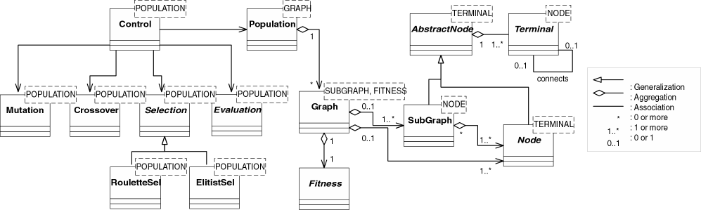
Figure 3. Class diagram of EGG framework. (Click for larger image.)
EGG applications
The concept of EGG is originally proposed for synthesizing electronic circuits, especially arithmetic circuits. We have already applied the EGG system to various circuit design problems as follows:
- Constant-coefficient multipliers (combinational circuits)
- Unsigned binary number system
- Binary SW number system
- Constant-coefficient multipliers (sequential circuits)
- Bit-serial adders and multiply-adders
- Multiple-valued arithmetic circuits
- Multiplier blocks for transposed FIR digital filters
Click here for animated example of population transition.
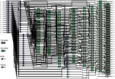
Figure 4. Evolved constant-coefficient multiplier.
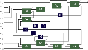
Figure 5. 10bit bit-serial adder.
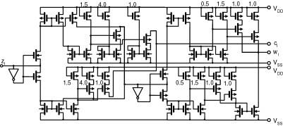
Figure 6. Current-mode radix-4 signed-digit full adder.